by Dave Tiessen, Mechanical Team Lead
The image below is rendered from the 3D computer model we created of our transatlantic sailboat (sailbot) hull earlier this year. Having a 3D model of our boat is great for helping us design and build the boat, but it has a lot more value than just that. It’s also very useful in facilitating a number of important analyses of our hull design. These include analyses of weight, weight distribution, and hydrostatics – all of which we will delve into in today’s blog post – as well as stability and sailing characteristics, which we will save for a future post.
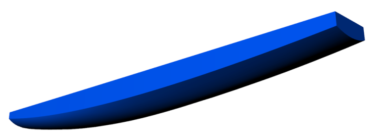
Figure 1 – Render from 3D CAD model of 2014 UBC SailBot hull
Estimating Weight
As with most engineering projects involving “things that go”, weight is an important parameter for SailBot. Amongst other things, the boat’s weight and weight distribution will affect the level and attitude it floats it, how it responds to waves, how it performs, and how much reserve it has in case of damage or heavy weather.
Estimating weight is an integral process of designing the boat. In the first stages of design, a desired length and rough shape of the hull are decided. Then an estimate of how much that hull will weigh can be made given its size and the materials it’s to be composed of. After that, all of the main components are listed and given an estimated weight. The total weight is tallied and a percentage, or margin, added for minor components and things we’ve missed. Next the weight estimate is compared to the estimated volume of the hull that will be underwater when floating as intended. This volume is called “displacement”. It’s how much water the boat displaces as it floats. For everything to work out, the weight of water displaced has to equal the weight of the boat.
Usually, on the first try, the weight and displacement don’t agree, so the dimensions of the hull are adjusted and the weight of the new hull estimated. This process is carried out iteratively until finally the displacement and weight agree. A spreadsheet with some formulas to estimate volume and weight based on hull dimensions and shape facilitates this process.
Since SailBot is meant to take part in a competition, there are some additional constraints on the initial design process. The rules of the Microtransat competition dictate that the waterline length of the hull cannot be over 4 metres. Fortunately, many of the required components in an autonomous sailboat are relatively light, so we were able to design the 2014 SailBot with a relatively low displacement for its length. That means that the hull can be narrow and shallow in the water, giving us the speedy shape we were after.
In the early stages of the weight and volume estimation cycle, the estimates are necessarily rough. As the cycle continues and the hull shape becomes better and better refined and defined, so do the estimates become better and better. The estimates of the weight of the hull are based on the weight per area of the materials used to build it. Now that the final shape of the hull is defined and precisely captured with a 3D CAD model, we can easily find the exact areas of the hull surfaces and the interior partitions. Furthermore, at this point in the design, most of the main internal components – electronics, servos, batteries and so on – have been specified, so we know their exact weights. This refinement of information contributing to the weight estimate allows us to make a fairly accurate assessment at this point.
The latest estimate of the completed weight of the 2014 Microtransat SailBot is 126 kg. This weight does not include the lead bulb that will be incorporated into the bottom of the keel. The keel bulb is a very important component contributing to the stability of the hull. The heavier the bulb, the less tippy the hull is. Originally, the bulb was planned to be 75 kg. But as the hydrostatic analysis presented below shows, that weight would make the SailBot about 10 kg too heavy. With a revised keel bulb weight of 65 kg, the keel bulb is still 1/3 of the total boat weight. Furthermore, SailBot’s keel is particularly deep, giving the bulb a long level arm which makes it more effective at keeping the boat upright. Stability analysis showed that even with this reduction to keel bulb weight, the SailBot will still be very stable. We will talk more about stability soon in an upcoming blog post.
Weight Distribution
Now we have a pretty good idea how much our boat will weigh. But total weight is not the whole story. The distribution of weight is also important. As you can imagine, if the boat weighs as much as the water it should displace but all of that weight is concentrated at the very back, the boat will not float on a level trim as intended. Earlier weight estimates could overlook distribution, because the final locations of most things were undecided: they could be moved to achieve a favourable distribution. Now that we are in the later stages of design, it’s important to take into account the location of each item of mass in order to determine the centre of gravity of the boat. The centre of gravity is an imaginary point at which we can pretend all of the mass of the boat is concentrated. It’s a useful concept when we want to investigate how applying forces to the hull will affect it.
In boat design, the centre of gravity is usually measured in three components:
- Longitudinal Centre of Gravity (LCG)
- Transverse Centre of Gravity (TCG), and
- Vertical Centre of Gravity (VCG)
Of the three, TCG is perhaps the most critical, but also the easiest to deal with. If the TCG is in the wrong place, the boat will lean to one side, or heel. However, it’s easy to know where the TCG has to be. Because SailBot, like most boats, is symmetrical from side to side, we know that the TCG needs to be along the centreline of the boat. Many components, such as the hull itself, will naturally be distributed such that the boat is balanced. As we design the location of other components, we can take care to make sure we have them balanced in order to maintain the TCG on the centreline of the boat.
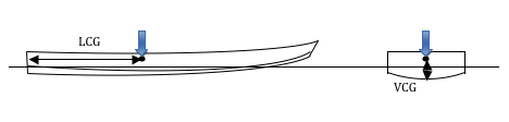
Figure 2 – Defining longitudinal and vertical centres of gravity: LCG and VCG
LCG is not so simple. The shapes of the forward and aft sections of the hull of SailBot, and of most boats, are not the same. So we can’t just assume LCG should be in the middle. To know where we want it, we need to get into hydrostatics, which we’ll talk about soon. But for now, we want to know where it is for the current design. The boat is much less sensitive to variation in the position of LCG than of TCG. If you think of pressing down on the middle of a long board floating in the water, you can imagine that it would be easy to make it roll quite a bit by moving your finger a bit to one side. It would take a lot more force, though, to raise one end of the board by moving your finger a bit towards the other end. However, it is still important to get the LCG in the right spot if we want to achieve our desired trim.
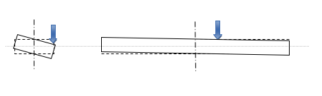
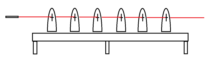
Figure 3 – Differences in effect of transverse and longitudinal offsets of weight
VCG makes no difference to heel or trim in static conditions. It is very important, though, when it comes to stability. The lower the VCG, the more stable the boat. Without the keel, SailBot’s VCG is about 12 cm above the waterline. That’s not bad for a boat with an 80 cm beam. But when the deep, heavy keel is added, SailBot’s VCG goes down to about 50 cm below the waterline. That makes the boat very stable and resistant to heeling – a good thing in a sailboat.
So how do we determine these centres of gravity? We’ll work with LCG as an example. First we choose a convenient place to measure from. In this case, the transom or back end of the boat. Then we measure the distance from the transom forward to each component. We multiply that distance by the weight of the component. That gives us a measure of the torque that would be required to hold that component up if it was at the end of a stick of that length. We then sum up all the torques, or moments, for all of the components. Now we have a measure of how much torque, or twisting force, you would have to apply to hold the boat up by its transom. If we divide that by the total weight of the boat, we are left with the distance forward from the transom that that total weight would have to act in order to produce the same torque. So if all that weight was concentrated into one single spot, it would have to be at our calculated distance forward to produce the same effect. That’s the definition of the LCG.

Figure 4 – The balance of weight multiplied by lever arm (image from wpclipart.com)
When the latest weight estimate for SailBot was completed, we calculated that the LCG was 1.79 m forward of the transom. That’s a little behind the middle of the boat, which is what we would expect.
Hydrostatics
In boat design, hydrostatics is principally concerned with the volume of water a hull displaces and with where the geometric centre of the displaced volume lies. These will change with the shape of the hull, of course, and with its depth in the water. Changing the attitude of the hull – its trim or heel – will also change its hydrostatic characteristics.
The reason we are interested in the volume of water a hull displaces is obvious: as mentioned earlier, the weight of water displaced must equal the weight of the boat. If we want our boat to float on its design waterline, we must ensure that the volume displaced with the hull at this depth is the same as the total weight of the boat. If the volume displaced is not enough, the boat will sink deeper to reach equilibrium. If the volume is too much, the boat will float too high unless more weight is added.
The reason for our interest in the geometric centre of the displaced volume may not be so obvious. That point is also known as the centre of buoyancy (CB). Just as we can imagine that all of the weight of an object is concentrated at its centre of gravity (CG), we can imagine that all of the buoyant force pushing the boat up is concentrated at its centre of buoyancy. If the CB is vertically aligned with the CG, then we can see that the downward force of gravity can be nicely balanced by the upward force of buoyancy along the same line. In this case, the boat will float steadily. However, if the CG and CB are not vertically aligned, the force of gravity and buoyancy will also not be aligned. The offset will create a torque that will roll the boat until the two forces are aligned.
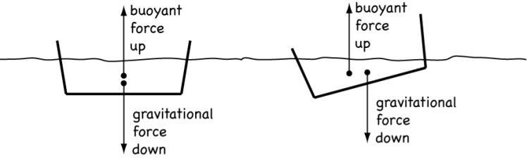
Figure 5 – Effect of misalignment ofcentre of gravity (CG) and centre of buoyancy (CB). Image modified from Harvard Natural Sciences Lecture Demonstrations – Fluid Statics
As you can see in the diagram above, this torque can work in our favour when the CB shifts to one side because the boat has heeled. In this case, the torque is known as a righting moment and helps to restore the boat to an even keel. But, if the CB for the boat floating at its intended waterline doesn’t match up with its CG, the boat will change its heel and trim until the two do line up. In other words, it won’t float in the intended attitude.
If our hull were rectangular or spherical or some other regular shape, finding its volume would be easy. But how do we find the volume of such an irregular shape as a boat hull? Well we break it into smaller problems and use some approximation. Let’s imagine finding the volume of another irregularly shaped object as an example: a loaf of bread. If we first slice the loaf of bread, we can measure the area of each slice. There are many ways to do this, but we can imagine tracing the slice on a piece of graph paper and then counting the squares inside our slice. If we multiply the area of the slice by its thickness, then we have a measure of its volume. At the ends of the loaf, where the surface curves in, our estimate won’t be so good, but we can make up for that by taking thinner slices. Once we’ve found the volume of all of the slices, we can add them up to find the volume of the entire loaf. Or, we could add the slices up to a certain point to measure the volume of the loaf up to that point.

Figure 6 – Finding volume by slices
The approach taken to find the volume of our boat is more-or-less the same as that described above. For the boat, though, we probably want to take horizontal slices on waterlines, rather than transverse slices like a loaf of bread. We can take very thin slices to make out estimate accurate, and we can add the slices up to any waterline we like to see how much volume we’ve displaced at that waterline.
Now how do we find the centre of buoyancy? We find it the same way as we found the centre of gravity. To find the longitudinal centre of buoyancy (LCB), we can use a 3D grid to divide our hull into cubes. Let’s say that each cube was a cubic centimetre. Each would then have a weight of one gram if made of water. So if the cube was instead displacing water, it would have an upward buoyant force of 1 gram. For each cube, we can multiply that force by its distance forward from the transom to find a torque. If we add up all the torques from each cube within the hull and divide them by the total displacement of the hull, we are left with a lever arm length: the LCB.
Of course doing all of this by hand would be very tedious. For SailBot we used a specialized software called GHS. It computes displacement and CB using a process analogous to what we’ve discussed above, but with very thin slices and very small cubes so the accuracy is high. GHS can actually do many more sophisticated analyses than these, but finding displacement and CB are a good start. Once we’ve found these we can find a number of other interesting parameters as well. Let’s start with a few of the key characteristics determined in our GHS analysis of the SailBot hull. These characteristics were measured with the boat at a baseline draft of 1.38 m. That means the lowest point of the hull is 1.38 m below the surface. This analysis discounts the boats keel, which of course would make it much deeper than that. We’ll go through the characteristics below to see what they can tell us.
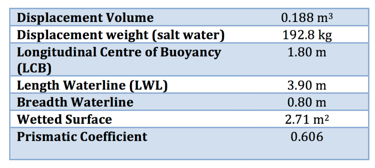
Table 1 – Hydrostatic characteristics of UBC 2014 SailBot hull at a baseline draft of 1.38 m
The displacement volume of 0.188 cubic metres or 188 litres is actually quite low for a hull as long as SailBot. When floating as designed, this means that the boat is narrow and shallow – helping to make it fast. It also hints at the fact that most of the hull’s volume is out of the water, giving it plenty of reserve buoyancy, particularly in the overhanging bow. That’s important for seaworthiness in rough weather, and to prevent the bow from digging in when the boat is sailing with a strong tailwind.
In fresh water, the displacement weight of the boat would be about 188 kg, because one litre of water is about one kilogram in weight. But since SailBot will sail in salt water, which is slightly heavier, its displacement weight at the design waterline is 192.8 kg. If we subtract the 126 kg determined in the latest weight estimate, that leaves about 66 kg for the keel bulb, as mentioned earlier.
The LCB of 1.80 m is very satisfying. You’ll notice that it’s almost exactly the same as what we found for LCG in the weight estimate. As we’ve discussed, that’s exactly what we want. This result means that we don’t need to change the planned layout of our current design significantly to achieve the right weight distribution. Our design will allow the heavy main battery to be slid forward or aft on its mountings to adjust for any small discrepancies in the final positions of LCG and LCB.
As mentioned earlier, the maximum waterline length allowed in the Microtransat competition is 4 m. We’ve designed SailBot with a 3.9 m LWL to have a safe margin below the limit. The maximum breadth of 0.8 m shows that SailBot is a relatively long and narrow hull with a length to beam ratio of about five to one. That fact is further apparent in the prismatic coefficient.
Prismatic coefficient (Cp) is a commonly use metric for quantifying the shape of a boat hull. It compares the displacement volume of the actual hull to the displacement of a prism of the same length that has a constant cross-sectional area equal to that of the maximum underwater section of the hull. The way to imagine this prism is to think of the largest underwater cross-section of the actual hull – usually around the middle of the boat. Now extrude this cross-section out in both directions to the bow and the stern of the boat with no tapering. Essentially what the prismatic coefficient tells us is how much the ends of the boat taper compared to its middle. Boats with fine ends have a low Cp. Boats will blunt ends have a higher Cp. SailBot’s prismatic coefficient of 0.606 is at the high end for sailboats, which are usually in the range from 0.5 to 0.6. However, that finding is misleading because SailBot also has a higher length to breadth ratio than most sailboats. A very long, narrow hull like an outrigger canoe will have a high Cp simply because the cross-section of the hull doesn’t change much along most of its length, though it may have very fine ends.
Wetted surface is just what is sounds like – the surface area of the hull that is underwater and “wet” when floating. This number is important in terms of drag. A high wetted surface will lead to high friction drag – important when sailing in light wind conditions. At higher speeds, however, other sources of drag become more important. The fin keel design of SailBot means that its wetted surface will be much less than that of an equivalent boat with a traditional full keel design.
Having determined wetted surface and volume displacement, we can now computer two final metrics of interest. These are sail area/wetted surface and sail area/(volume displacement)2/3 – two common metrics used for sizing yacht sails. The currently planned sail for the 2014 SailBot is a windsurfing rig with an area of 5.9 m2. Computing the metrics with this sail area and the data from Table 1 above gives the following results.
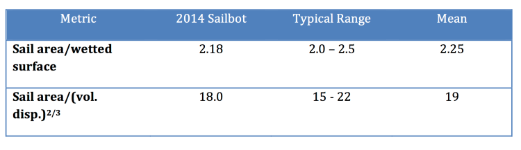
Table 2 – Comparison of sail size metrics for SailBot to typical values for sailboats. Typical values are taken from Principles of Yacht Design by Lars Larsson and Rolf Eliasson.
These results show that SailBot is squarely in the middle of typical ranges for sailboats in terms of sail area to hull size. However, SailBot has a much deeper keel for its hull size than typical sailboats. That means the boat could handle a larger sail in normal conditions. However, since SailBot must cross the notoriously rough North Atlantic without maintenance, it’s best to keep the sail area conservative. Stay tuned for the upcoming stability blog post for more about the benefits of SailBot’s deep keel.